The transmission is a device that
is connected to the back of the engine and sends the power from the engine to
the drive wheels. An automobile engine runs at its best at a certain RPM
(Revolutions Per Minute) range and it is the transmission's job to make sure
that the power is delivered to the wheels while keeping the engine within that
range. It does this through various gear combinations. In first gear, the
engine turns much faster in relation to the drive wheels, while in high gear the
engine is loafing even though the car may be going in excess of 70 MPH. In
addition to the various forward gears, a transmission also has a neutral
position which disconnects the engine from the drive wheels, and reverse, which
causes the drive wheels to turn in the opposite direction allowing you to back
up. Finally, there is the Park position. In this position, a latch mechanism
(not unlike a deadbolt lock on a door) is inserted into a slot in the output
shaft to lock the drive wheels and keep them from turning, thereby preventing
the vehicle from rolling.
There are two basic types of automatic
transmissions based on whether the vehicle is rear wheel drive or front
wheel drive.
On a rear wheel drive
car, the transmission is usually mounted to the back of the engine and is
located under the hump in the center of the floorboard alongside the gas pedal
position. A drive shaft connects the rear of the transmission to the final
drive which is located in the rear axle and is used to send power to the rear
wheels. Power flow on this system is simple and straight forward going from the
engine, through the torque converter, then through the transmission and drive
shaft until it reaches the final drive where it is split and sent to the two
rear wheels.
On a front wheel drive
car, the transmission is usually combined with the final drive to form what is
called a transaxle. The engine on a front wheel drive car is usually mounted
sideways in the car with the transaxle tucked under it on the side of the engine
facing the rear of the car.
Front axles are connected directly to the
transaxle and provide power to the front wheels. In this example, power flows
from the engine, through the torque converter to a large chain that sends the
power through a 180 degree turn to the transmission that is along side the
engine. From there, the power is routed through the transmission to the final
drive where it is split and sent to the two front wheels through the drive
axles.
There are a number of
other arrangements including front drive vehicles where the engine is mounted
front to back instead of sideways and there are other systems that drive all
four wheels but the two systems described here are by far the most popular. A
much less popular rear drive arrangement has the transmission mounted directly
to the final drive at the rear and is connected by a drive shaft to the torque
converter which is still mounted on the engine. This system is found on the new
Corvette and is used in order to balance the weight evenly between the front and
rear wheels for improved performance and handling. Another rear drive system
mounts everything, the engine, transmission and final drive in the rear. This
rear engine arrangement is popular on the Porsche.
The modern automatic
transmission consists of many components and systems that are designed to work
together in a symphony of clever mechanical, hydraulic and electrical technology
that has evolved over the years into what many mechanically inclined individuals
consider to be an art form. We try to use simple, generic explanations where
possible to describe these systems but, due to the complexity of some of these
components, you may have to use some mental gymnastics to visualize their
operation.
The main components that
make up an automatic transmission include:
Planetary Gear Sets
which are the mechanical systems that provide the various forward gear ratios as
well as reverse.
The
Hydraulic System
which uses a special transmission fluid sent under pressure by an
Oil Pump through
the
Valve Body to
control the
Clutches and the
Bands in order to
control the planetary gear sets.
Seals and Gaskets
are used to keep the oil where it is supposed to be and prevent it from leaking
out.
The
Torque Converter
which acts like a clutch to allow the vehicle to come to a stop in gear while
the engine is still running.
The
Governor and the
Modulator or
Throttle Cable that
monitor speed and throttle position in order to determine when to shift.
On newer vehicles, shift
points are controlled by
Computer which
directs electrical solenoids to shift oil flow to the appropriate component at
the right instant.
Automatic transmissions
contain many gears in various combinations. In a manual transmission,
gears slide along shafts as you move the shift lever from one position to
another, engaging various sized gears as required in order to provide the
correct gear ratio. In an automatic transmission, however, the gears are never
physically moved and are always engaged to the same gears. This is accomplished
through the use of planetary gear sets.
The basic planetary
gear set consists of a sun gear, a ring gear and two or more planet gears,
all remaining in constant mesh. The planet gears are connected to each other
through a common carrier which allows the gears to spin on shafts called
"pinions" which are attached to the carrier .
One example of a way that
this system can be used is by connecting the ring gear to the input shaft coming
from the engine, connecting the planet carrier to the output shaft, and locking
the sun gear so that it can't move. In this scenario, when we turn the ring
gear, the planets will "walk" along the sun gear (which is held stationary)
causing the planet carrier to turn the output shaft in the same direction as the
input shaft but at a slower speed causing gear reduction (similar to a car in
first gear).
If we unlock the sun gear
and lock any two elements together, this will cause all three elements to turn
at the same speed so that the output shaft will turn at the same rate of speed
as the input shaft. This is like a car that is in third or high gear. Another
way that we can use a Planetary gear set is by locking the planet carrier from
moving, then applying power to the ring gear which will cause the sun gear to
turn in the opposite direction giving us reverse gear.
The illustration on the
right shows how the simple system described above would look in an actual
transmission. The input shaft is connected to the ring gear (Blue),
The Output shaft is connected to the planet carrier (Green)
which
is also connected to a "Multi-disk" clutch pack. The sun gear is connected to a
drum (yellow) which is also
connected to the other half of the clutch pack. Surrounding the outside of the
drum is a band (red) that can
be tightened around the drum when required to prevent the drum with the attached
sun gear from turning.
The clutch pack is used,
in this instance, to lock the planet carrier with the sun gear forcing both to
turn at the same speed. If both the clutch pack and the band were released, the
system would be in neutral. Turning the input shaft would turn the planet gears
against the sun gear, but since nothing is holding the sun gear, it will just
spin free and have no effect on the output shaft. To place the unit in first
gear, the band is applied to hold the sun gear from moving. To shift from first
to high gear, the band is released and the clutch is applied causing the output
shaft to turn at the same speed as the input shaft.
Many more combinations
are possible using two or more planetary sets connected in various ways to
provide the different forward speeds and reverse that are found in modern
automatic transmissions.
Some of the clever gear
arrangements found in four and now, five, six and even seven and eight-speed
automatics are complex enough to make a technically astute lay person's head
spin trying to understand the flow of power through the transmission as it
shifts from first gear through top gear while the vehicle accelerates to highway
speed. On modern vehicles (mid '80s to the present), the vehicle's computer
monitors and controls these shifts so that they are almost imperceptible.
A
clutch pack consists of alternating disks that fit inside a clutch drum.
Half of the disks are steel and have splines that fit into groves on the inside
of the drum. The other half have a friction material bonded to their surface
and have splines on the inside edge that fit groves on the outer surface of the
adjoining hub. There is a piston inside the drum that is activated by oil
pressure at the appropriate time to squeeze the clutch pack together so that the
two components become locked and turn as one.
A one-way clutch
(also known as a "sprag" clutch) is a device that will allow a component such as
ring gear to turn freely in one direction but not in the other. This effect is
just like that of a bicycle, where the pedals will turn the wheel when pedaling
forward, but will spin free when pedaling backward.
A common place where a
one-way clutch is used is in first gear when the shifter is in the drive
position. When you begin to accelerate from a stop, the transmission starts out
in first gear. But have you ever noticed what happens if you release the gas
while it is still in first gear? The vehicle continues to coast as if you were
in neutral. Now, shift into Low gear instead of Drive. When you let go of the
gas in this case, you will feel the engine slow you down just like a standard
shift car. The reason for this is that in Drive, a one-way clutch is used
whereas in Low, a clutch pack or a band is used.
A band is a steel
strap with friction material bonded to the inside surface. One end of the band
is anchored against the transmission case while the other end is connected to a
servo. At the appropriate time hydraulic oil is sent to the servo under
pressure to tighten the band around the drum to stop the drum from turning.
On
automatic transmissions, the torque converter takes the place of the
clutch found on standard shift vehicles. It is there to allow the engine to
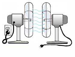
continue running when the vehicle comes to a stop. The principle behind a
torque converter is like taking a fan that is plugged into the wall and blowing
air into another fan which is unplugged. If you grab the blade on the unplugged
fan, you are able to hold it from turning but as soon as you let go, it will
begin to speed up until it comes close to the speed of the powered fan. The
difference with a torque converter is that instead of using air, it uses oil or
transmission fluid, to be more precise.
A torque converter is a
large doughnut shaped device (10" to 15" in diameter) that is mounted between
the engine and the transmission. It consists of three internal elements that
work together to transmit power to the transmission. The three elements of the
torque converter are the Pump, the Turbine, and the Stator. The pump is
mounted directly to the converter housing which in turn is bolted directly to
the engine's crankshaft and turns at engine speed. The turbine is inside the
housing and is connected directly to the input shaft of the transmission
providing power to move the vehicle. The stator is mounted to a one-way clutch
so that it can spin freely in one direction but not in the other. Each of the
three elements have fins mounted in them to precisely direct the flow of oil
through the converter
With the engine running,
transmission fluid is pulled into the pump section and is pushed outward by
centrifugal force until it reaches the turbine section which starts it turning.
The fluid continues in a circular motion back towards the center of the turbine
where it enters the stator. If the turbine is moving considerably slower than
the pump, the fluid will make contact with the front of the stator fins which
push the stator into the one way clutch and prevent it from turning. With the
stator stopped, the fluid is directed by the stator fins to re-enter the pump at
a "helping" angle providing a torque increase. As the speed of the turbine
catches up with the pump, the fluid starts hitting the stator blades on the
back-side causing the stator to turn in the same direction as the pump and
turbine. As the speed increases, all three elements begin to turn at
approximately the same speed.
Since the '80s, in order
to improve fuel economy, torque converters have been equipped with a lockup
clutch (not shown) which locks the turbine to the pump as the vehicle speed
reaches approximately 45 - 50 MPH. This lockup is controlled by computer and
usually won't engage unless the transmission is in 3rd or 4th gear.
The Hydraulic system
is a complex maze of passages and tubes that sends transmission fluid under
pressure to all parts of the transmission and torque converter. The diagram at
left is a simple one from a 3-speed automatic from the '60s. The newer systems
are much more complex and are combined with computerized electrical components.
Transmission fluid serves a number of purposes including: shift control, general
lubrication and transmission cooling. Unlike the engine, which uses oil
primarily for lubrication, every aspect of a transmission's functions are
dependant on a constant supply of fluid under pressure. This is not unlike the
human circulatory system (the fluid is even red) where even a few minutes of
operation when there is a lack of pressure can be harmful or even fatal to the
life of the transmission. In order to keep the transmission at normal
operating temperature, a portion of the fluid is sent through one of two steel
tubes to a special chamber that is submerged in anti-freeze in the radiator.
Fluid passing through this chamber is cooled and then returned to the
transmission through the other steel tube. A typical transmission has an
average of ten quarts of fluid between the transmission, torque converter, and
cooler tank. In fact, most of the components of a transmission are constantly
submerged in fluid including the clutch packs and bands. The friction surfaces
on these parts are designed to operate properly only when they are submerged in
oil.
The transmission oil
pump (not to be confused with the pump element inside the torque converter)
is responsible for producing all the oil pressure that is required in the
transmission. The oil pump is mounted to the front of the transmission case and
is directly connected to a flange on the torque converter housing. Since the
torque converter housing is directly connected to the engine crankshaft, the
pump will produce pressure whenever the engine is running as long as there is a
sufficient amount of transmission fluid available. The oil enters the pump
through a filter that is located at the bottom of the transmission oil pan and
travels up a pickup tube directly to the oil pump. The oil is then sent, under
pressure to the pressure regulator, the valve body and the rest of the
components, as required.
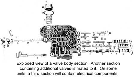
The valve body is
the control center of the automatic transmission. It contains a maze of
channels and passages that direct hydraulic fluid to the
numerous valves which then activate the appropriate clutch pack or band servo to
smoothly shift to the appropriate gear for each driving situation. Each of the
many valves in the valve body has a specific purpose and is named for that
function. For example the 2-3 shift valve activates the 2nd gear to 3rd gear
up-shift or the 3-2 shift timing valve which determines when a downshift should
occur.
The most important valve,
and the one that you have direct control over is the manual valve. The manual
valve is directly connected to the gear shift handle and covers and uncovers
various passages depending on what position the gear shift is placed in. When
you place the gear shift in Drive, for instance, the manual valve directs fluid
to the clutch pack(s) that activates 1st gear. it also sets up to monitor
vehicle speed and throttle position so that it can determine the optimal time
and the force for the 1 - 2 shift. On computer controlled transmissions, you
will also have electrical solenoids that are mounted in the valve body to
direct fluid to the appropriate clutch packs or bands under computer control to
more precisely control shift points.
The
computer uses sensors on the engine and transmission to detect such things as
throttle position, vehicle speed, engine speed, engine load, brake pedal
position, etc. to control exact shift points as well as how soft or firm the
shift should be. Once the computer receives this information, it then sends
signals to a solenoid pack inside the transmission. The solenoid pack contains
several electrically controlled solenoids that redirect the fluid to the
appropriate clutch pack or servo in order to control shifting. Computerized
transmissions even learn your driving style and constantly adapt to it so that
every shift is timed precisely when you would need it.
Because of computer
controls, sports models are coming out with the ability to take manual
control of the transmission as though it were a stick shift, allowing the driver
to select gears manually. This is accomplished on some cars by passing the
shift lever through a special gate, then tapping it in one direction or the
other in order to up-shift or down-shift at will. The computer monitors this
activity to make sure that the driver does not select a gear that could over
speed the engine and damage it.
Another advantage to
these "smart" transmissions is that they have a self diagnostic mode which can
detect a problem early on and warn you with an indicator light on the dash. A
technician can then plug test equipment in and retrieve a list of trouble codes
that will help pinpoint where the problem is.
These three components
are important in the non-computerized transmissions. They provide the inputs
that tell the transmission when to shift. The Governor is connected to
the output shaft and regulates hydraulic pressure based on vehicle speed. It
accomplishes this using centrifugal force to spin a pair of hinged weights
against pull-back springs. As the weights pull further out against the springs,
more oil pressure is allowed past the governor to act on the shift valves that
are in the valve body which then signal the appropriate shifts. Of course,
vehicle speed is not the only thing that controls when a transmission should
shift, the load that the engine is under is also important. The more load you
place on the engine, the longer the transmission will hold a gear before
shifting to the next one.
There are two types of
devices that serve the purpose of monitoring the engine load: the Throttle
Cable and the Vacuum Modulator. A transmission will use one or the
other but generally not both of these devices. Each works in a different way to
monitor engine load. The Throttle Cable simply monitors the position of the gas
pedal through a cable that runs from the gas pedal to the throttle valve in the
valve body. The Vacuum Modulator monitors engine vacuum by a rubber vacuum hose
which is connected to the engine. Engine vacuum reacts very accurately to
engine load with high vacuum produced when the engine is under light load and
diminishing down to zero vacuum when the engine is under a heavy load. The
modulator is attached to the outside of the transmission case and has a shaft
which passes through the case and attaches to the throttle valve in the valve
body. When an engine is under a light load or no load, high vacuum acts on the
modulator which moves the throttle valve in one direction to allow the
transmission to shift early and soft. As the engine load increases, vacuum is
diminished which moves the valve in the other direction causing the transmission
to shift later and more firmly.
An automatic
transmission has many seals and gaskets to control the flow of
hydraulic fluid and to keep it from leaking out. There are two main
external seals: the front seal and the rear seal. The front seal seals the point
where the torque converter mounts to the transmission case. This seal allows
fluid to freely move from the converter to the transmission but keeps the fluid
from leaking out. The rear seal keeps fluid from leaking past the output shaft.
A seal is usually
made of rubber (similar to the rubber in a windshield wiper blade) and is used
to keep oil from leaking past a moving part such as a spinning shaft. In some
cases, the rubber is assisted by a spring that holds the rubber in close contact
with the spinning shaft.
A gasket is a type
of seal used to seal two stationary parts that are fastened together. Some
common gasket materials are: paper, cork, rubber, silicone and soft metal.
Aside from the main seals,
there are also a number of other seals and gaskets that vary from transmission
to transmission. A common example is the rubber O-ring that seals the
shaft for the shift control lever. This is the shaft that you move when you
manipulate the gear shifter. Another example that is common to most
transmissions is the oil pan gasket. In fact, seals are required
anywhere that a device needs to pass through the transmission case with each one
being a potential source for leaks.


 is also connected to a "Multi-disk" clutch pack. The sun gear is connected to a
drum (
is also connected to a "Multi-disk" clutch pack. The sun gear is connected to a
drum (
 On
automatic transmissions, the torque converter takes the place of the
clutch found on standard shift vehicles. It is there to allow the engine to
continue running when the vehicle comes to a stop. The principle behind a
torque converter is like taking a fan that is plugged into the wall and blowing
air into another fan which is unplugged. If you grab the blade on the unplugged
fan, you are able to hold it from turning but as soon as you let go, it will
begin to speed up until it comes close to the speed of the powered fan. The
difference with a torque converter is that instead of using air, it uses oil or
transmission fluid, to be more precise.
On
automatic transmissions, the torque converter takes the place of the
clutch found on standard shift vehicles. It is there to allow the engine to
continue running when the vehicle comes to a stop. The principle behind a
torque converter is like taking a fan that is plugged into the wall and blowing
air into another fan which is unplugged. If you grab the blade on the unplugged
fan, you are able to hold it from turning but as soon as you let go, it will
begin to speed up until it comes close to the speed of the powered fan. The
difference with a torque converter is that instead of using air, it uses oil or
transmission fluid, to be more precise. 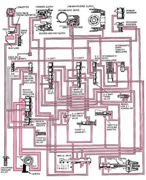
 numerous valves which then activate the appropriate clutch pack or band servo to
smoothly shift to the appropriate gear for each driving situation. Each of the
many valves in the valve body has a specific purpose and is named for that
function. For example the 2-3 shift valve activates the 2nd gear to 3rd gear
up-shift or the 3-2 shift timing valve which determines when a downshift should
occur.
numerous valves which then activate the appropriate clutch pack or band servo to
smoothly shift to the appropriate gear for each driving situation. Each of the
many valves in the valve body has a specific purpose and is named for that
function. For example the 2-3 shift valve activates the 2nd gear to 3rd gear
up-shift or the 3-2 shift timing valve which determines when a downshift should
occur. The
computer uses sensors on the engine and transmission to detect such things as
throttle position, vehicle speed, engine speed, engine load, brake pedal
position, etc. to control exact shift points as well as how soft or firm the
shift should be. Once the computer receives this information, it then sends
signals to a solenoid pack inside the transmission. The solenoid pack contains
several electrically controlled solenoids that redirect the fluid to the
appropriate clutch pack or servo in order to control shifting. Computerized
transmissions even learn your driving style and constantly adapt to it so that
every shift is timed precisely when you would need it.
The
computer uses sensors on the engine and transmission to detect such things as
throttle position, vehicle speed, engine speed, engine load, brake pedal
position, etc. to control exact shift points as well as how soft or firm the
shift should be. Once the computer receives this information, it then sends
signals to a solenoid pack inside the transmission. The solenoid pack contains
several electrically controlled solenoids that redirect the fluid to the
appropriate clutch pack or servo in order to control shifting. Computerized
transmissions even learn your driving style and constantly adapt to it so that
every shift is timed precisely when you would need it.